


The Ritemp System has International Patents applicable. Persons or Organizations who are found to be in breach of this patents will be
prosecuted to the full extent of the International patent laws. © Copyright Ritemp, 2021 and "Ritemp" is a Trademark of Ritemp Pty Ltd


See Brochure
Here


Thermodynamic calculations for a mold which uses the Ritemp
TM
Conformal Cooling System
The
thermodynamics
of
a
mold
which
uses
this
system
are
very
simple.
As
a
result,
comparatively
simple
mathematical
modelling
can
be used to determine heat exchanger specifications and to make meaningful predictions of molding cycle times.
The
two
primary
factors
which
control
the
time
required
for
a
molding
to
‘cure’
are
the
wall
thickness
of
the
part
and
the
ability
of
the
mold to dissipate heat.
The ‘curing‘ time in seconds for a part of wall thickness W cm can be calculated using the following formula:-
t
c
= 1.017 x {(ρ x c / k
p
)
1/2
x W / π}
2
x Ln{4 x (T
m
-T
d
) / (T
c
-T
d
) / π}
(1)
Where
T
m
= temperature of the molten plastic material (
o
C).
T
d
= average working temperature of the molding surface (
o
C).
T
c
= temperature required at centre of the part’s wall for safe ejection from the mold (
o
C).
ρ = density of the plastic material (gm/cm
3
) (At the melt temperature)
c = specific heat of the plastic material (Joules/gm/
o
C). (At the melt temperature)
k
p
= thermal conductivity of the plastic material (Watts/cm/
o
C).
Note-
equation
(1)
is
an
approximation
derived
from
an
equation
which
contains
the
sum
of
a
highly
convergent
infinite
(Fourier)
series.
For
values
of
T
c
which
are
less
than
60%
of
T
m
,
results
are
correct
to
3
significant
figures.
This
condition
is
met
for
all
practical
values of T
c
. Also, the assumption is made that full contact is maintained between the part and the mold.
Consider a part molded from polypropylene at a melt temperature of 230
o
C.
For polypropylene,
ρ = 0.89 gm/cm
3
c = 2.1 Joules/gm/
o
C
k
p
= 0.001138 Watts/cm/
o
C
Using 120
o
C as the value for T
c
, the curing time can then be calculated for any given combination of wall thickness and mold surface
temperature.
We then need to calculate the rate at which the plastic part gives up heat to the mold.
The amount of heat lost to the mold by a 1cm
2
section of the part is given by:-
H = (T
m
-(T
c
+T
d
) / 2) x W x p x c Joules
(2)
(For
simplicity
it
has
been
assumed
that
the
temperature
profile
through
the
wall
of
the
part
is
linear.
The
error
caused
by
this
approximation results in a slight overestimation of the value of H).
Knowing the curing time and the molding machine’s operating speeds, the total cycle time can then be estimated.
Let’s consider an example part which is 1 mm thick, molded in a mold which has its average surface temperature maintained at 45
o
C.
From
equation
(1)
the
cure
time
for
the
part
is
1.9
sec.
The
time
required
to
open
the
mold,
eject
the
part
and
close
it
again
would
account
for
say,
an
additional
2
seconds
and,
depending
on
the
size
of
the
part,
a
further
time
of
say,
0,6
seconds
would
be
required
for
filling
the
cavity.
Assuming
that
the
machine’s
screw
recovery
time
is
not
a
limiting
factor,
this
gives
an
estimated
total
cycle
time,
C, of 4.5 seconds.
From
equation
(2)
the
value
of
H
is
27.6
Joules/cm
2
.
This
heat
is
transferred
to
the
mold
in
about
1,9sec.
The
mold,
however,
has
4.5
seconds in which to dissipate that heat.
The rate of dissipation of heat by the mold, Q, is then given by
Q = H/C = 27.6 / 4.5 = 6.13 Watts/cm
2
.
Since
that
heat
is
directed
in
two
directions
(to
the
2
halves
of
the
mold)
we
can
then
deduce
that
each
half
of
the
mold
needs
to
dissipate
heat
at
the
rate
of
3.07
Watts
for
each
square
cm
of
plastic
in
contact
with
it.
(If
the
part
has
significant
ribbing
on
one
side,
then
the
sharing
proportions
would
need
to
be
adjusted accordingly). Let q be this share of the total.
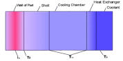
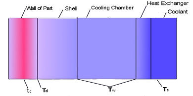
If
the
effective
distance
from
the
mold’s
working
surface
to
its
cooling
chamber
is
D
then
the
temperature
of
the
cooling
chamber
(T
w
)
will
need
to
be
maintained at a level given by the following equation:-
T
w
= T
d
– D x q / k
m
(3)
Where k
m
= Thermal conductivity of the mold material.
For a mold manufactured from P20 steel, k
m
= 3.79Watts/mm/
o
C
If D has a value of 15mm then from equation (3) the value of T
w
is 32.8
o
C.
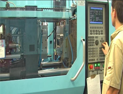
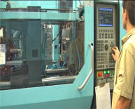
Functional test using Demo Unit, February 2022
The demo unit has four cylindrical cores, a typical structure for the moving side of molds.
A
Ritemp
TM
Controller
was
used
to
monitor
the
cooling
chamber
temperature
(T
w
),
while
blow
torches
were
applied
to
each
core
and
iced
water
coolant
was
pumped
through
the
heat
exchanger.
The
output
of
the
torches
was
set
to
achieve
a
steady
indicated
T
w
of
35
o
C.
One
channel
of
an
accurate
2
channel
pyrometer
monitored
the
temperature
of
the
water
entering
the
heat
exchanger
while
the
other
channel monitored the water leaving it. This instrument indicated a
ΔT of 2.45
o
C.
The
coolant
flow
rate
(F)
was
determined
by
measuring
the
time
taken
for
a
measured
volume
of
coolant
to
pass
through
the
heat
exchanger.
F = 13,750 / 83 = 165.7 cc/sec
The heat dissipation rate D is then given by:-
D = F x
ΔT x 4.184 = 165.7 x 2.45
x 4.184
= 1,700 watts
.


Some of these pages UNDER CONSTRUCTION


Thermodynamic calculations for a mold which uses the Ritemp
TM
Conformal
Cooling System
The
thermodynamics
of
a
mold
which
uses
this
system
are
very
simple.
As
a
result,
comparatively
simple
mathematical
modelling
can
be
used
to
determine
heat
exchanger
specifications
and
to
make
meaningful
predictions
of
molding
cycle
times.
The
two
primary
factors
which
control
the
time
required
for
a
molding
to
‘cure’
are
the wall thickness of the part and the ability of the mold to dissipate heat.
The
‘curing‘
time
in
seconds
for
a
part
of
wall
thickness
W
cm
can
be
calculated
using the following formula:-
t
c
= 1.017 x {(ρ x c / k
p
)
1/2
x W / π}
2
x Ln{4 x (T
m
-T
d
) / (T
c
-T
d
) / π}
(1)
Where
T
m
= temperature of the molten plastic material (
o
C).
T
d
= average working temperature of the molding surface (
o
C).
T
c
= temperature required at centre of the part’s wall for safe ejection from the
mold (
o
C).
ρ = density of the plastic material (gm/cm
3
) (At the melt temperature)
c = specific heat of the plastic material (Joules/gm/
o
C). (At the melt
temperature)
k
p
= thermal conductivity of the plastic material (Watts/cm/
o
C).
Note-
equation
(1)
is
an
approximation
derived
from
an
equation
which
contains
the
sum
of
a
highly
convergent
infinite
(Fourier)
series.
For
values
of
T
c
which
are
less
than
60%
of
T
m
,
results
are
correct
to
3
significant
figures.
This
condition
is
met
for
all
practical
values
of
T
c
.
Also,
the
assumption
is
made
that
full
contact
is
maintained between the part and the mold.
Consider a part molded from polypropylene at a melt temperature of 230
o
C.
For polypropylene,
ρ = 0.89 gm/cm
3
c = 2.1 Joules/gm/
o
C
k
p
= 0.001138 Watts/cm/
o
C
Using 120
o
C as the value for T
c
, the curing time can then be calculated for any
given combination of wall thickness and mold surface temperature.
We then need to calculate the rate at which the plastic part gives up heat to the
mold.
The amount of heat lost to the mold by a 1cm
2
section of the part is given by:-
H = (T
m
-(T
c
+T
d
) / 2) x W x p x c Joules
(2)
(For
simplicity
it
has
been
assumed
that
the
temperature
profile
through
the
wall
of
the
part
is
linear.
The
error
caused
by
this
approximation
results
in
a
slight
overestimation of the value of H).
Knowing
the
curing
time
and
the
molding
machine’s
operating
speeds,
the
total
cycle time can then be estimated.
Let’s
consider
an
example
part
which
is
1
mm
thick,
molded
in
a
mold
which
has
its
average surface temperature maintained at 45
o
C.
From
equation
(1)
the
cure
time
for
the
part
is
1.9
sec.
The
time
required
to
open
the
mold,
eject
the
part
and
close
it
again
would
account
for
say,
an
additional
2
seconds
and,
depending
on
the
size
of
the
part,
a
further
time
of
say,
0,6
seconds
would
be
required
for
filling
the
cavity.
Assuming
that
the
machine’s
screw
recovery
time
is
not
a
limiting
factor,
this
gives
an
estimated
total
cycle
time,
C,
of
4.5 seconds.
From
equation
(2)
the
value
of
H
is
27.6
Joules/cm
2
.
This
heat
is
transferred
to
the
mold
in
about
1,9sec.
The
mold,
however,
has
4.5
seconds
in
which
to
dissipate
that heat.
The rate of dissipation of heat by the mold, Q, is
then given by
Q = H/C = 27.6 / 4.5 = 6.13 Watts/cm
2
.
Since
that
heat
is
directed
in
two
directions
(to
the
2
halves
of
the
mold)
we
can
then
deduce
that
each
half
of
the
mold
needs
to
dissipate
heat
at
the
rate
of
3.07
Watts
for
each
square
cm
of
plastic
in
contact
with
it.
(If
the
part
has
significant
ribbing
on
one
side,
then
the
sharing
proportions
would
need
to
be
adjusted accordingly). Let q be this share of the total.
If
the
effective
distance
from
the
mold’s
working
surface
to
its
cooling
chamber
is
D
then
the
temperature
of
the
cooling
chamber
(T
w
)
will
need
to
be
maintained
at
a
level given by the following equation:-
T
w
= T
d
– D x q / k
m
(3)
Where k
m
= Thermal conductivity of the mold material.
For a mold manufactured from P20 steel, k
m
= 3.79Watts/mm/
o
C
If D has a value of 15mm then from equation (3) the value of T
w
is 32.8
o
C.
Functional test using Demo Unit, February 2022
The
demo
unit
has
four
cylindrical
cores,
a
typical
structure
for
the
moving
side
of
molds.
A
Ritemp
TM
Controller
was
used
to
monitor
the
cooling
chamber
temperature
(T
w
),
while
blow
torches
were
applied
to
each
core
and
iced
water
coolant
was
pumped
through
the
heat
exchanger.
The
output
of
the
torches
was
set
to
achieve
a
steady
indicated T
w
of 35
o
C.
One
channel
of
an
accurate
2
channel
pyrometer
monitored
the
temperature
of
the
water
entering
the
heat
exchanger
while
the
other
channel
monitored
the
water
leaving it. This instrument indicated a
ΔT of 2.45
o
C.
The
coolant
flow
rate
(F)
was
determined
by
measuring
the
time
taken
for
a
measured volume of coolant to pass through the heat exchanger.
F = 13,750 / 83 = 165.7 cc/sec
The heat dissipation rate D is then given by:-
D = F x
ΔT x 4.184 = 165.7 x 2.45
x 4.184
= 1,700 watts
.